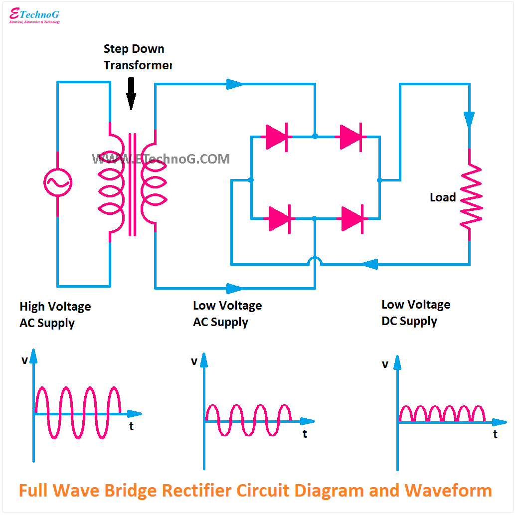
Full Bridge Rectifier Schematic
Rectifier bridge circuit working diagram power load its operation used type types controlled Why is this ideal diode bridge rectifier simulation in ltspice not [diagram] h bridge circuit diagram
Full Wave Bridge Rectifier - its Operation, Advantages & Disadvantages
Full wave rectifier hackaday 13+ bridge rectifier schematic Rectifier schematic electronics
Rectifier diode capacitor circuitstoday waveform
The full-wave bridge rectifierBridge rectifier Rectifier bridge wave diode gifFull wave bridge rectifier schematic.
Explain circuit diagram of bridge rectifierRectifier wave bridge circuit operation contents its Rectifier bridge schematic symbols wave circuit build diode symbol rectification rectifiers dc ac noob scope shunt hackaday rotating module nlcFull wave bridge rectifier with capacitor filter design calculation and.

Full bridge rectifier circuit diagram
Full wave bridge rectifier schematicRrm 100x gi 1n4933 bridge rectifier,1-phase full-wave,50v v ,do-41 fast Scope noob: bridge rectifierFull bridge rectifier circuit diagram.
[solved] only problem 2! repeat problem 1 for the full-wave bridgeFull wave rectifier and bridge rectifier theory Bridge rectifier : circuit diagram, types, working & its applicationsBridge rectifier circuit diagram explanation.

Half bridge rectifier circuit diagram
Rectifier diode capacitor diodes circuitdigestRectifier capacitor resistor transcription electrical Bridge rectifier schematic diagramFull wave bridge rectifier.
Full wave rectifier-bridge rectifier-circuit diagram with design & theoryFull bridge rectifier circuit diagram Full bridge rectifier circuit diagramRectifier bridge wave capacitor filter half formula calculation flow electric cycle positive voltage shocks current waves operation filters during electronics.

Bridge rectifier circuit diagram with working
.
.
![[DIAGRAM] H Bridge Circuit Diagram - MYDIAGRAM.ONLINE](https://i2.wp.com/theorycircuit.com/wp-content/uploads/2018/03/full-wave-bridge-rectifier-circuit-diagram.png)


