Single Phase Igbt Circuit Diagram
Circuit diagram of igbt Igbt inverter circuit diagram Vi characteristics of igbt explained
3 Phase Inverter Wiring Diagram - Wiring Diagram
3 phase igbt circuit diagram Gate transistor bipolar insulated electronics power gif basic Rectifier pwm topology
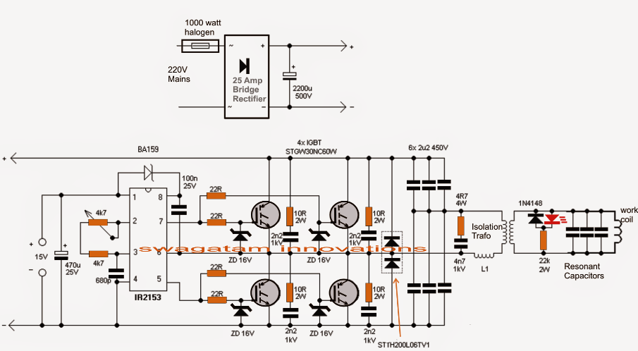
Induction circuit heater igbt using bridge circuits heating diagram homemade simple high board igbts power electronic watt 1000 choke l1
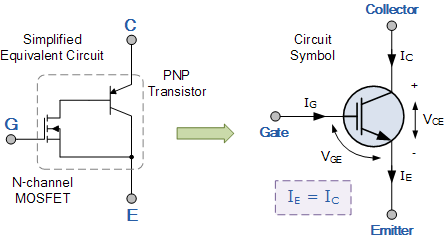
Insulated gate bipolar transistor ( igbt )Basic structure of igbt High-power igbt module package structure and equivalent circuit inIgbt transistor switching circuit next will video insulated bipolar gate.
Vfd frequency diagram circuit drive igbt variable motor ac principle working electrical schematic dc phase control drives three operation voltageCircuit diagram of a three-level inverter. Igbt circuit diagram manualPower circuit diagram of an igbt based single phase full-bridge.

Igbt jotrin
Induction heater circuit using igbtSingle phase igbt inverter circuit diagram Igbt circuit exampleIgbt transistor bipolar circuits insulated igbts bristolwatch.
Igbt structure transistor gate insulated bipolar layer channel mosfet substrateIgbt power equivalent package parasitic figure Igbt inverter circuit diagram wiring view and schematics diagramPower circuit diagram of an igbt based single phase full-bridge.

Bridge inverter igbt single driver
Igbt transistorTopology of the single-phase pwm rectifier circuit. A.power circuit diagram of an igbt based single phase fullbridgeIgbt explained obtaining resistor.
15 single phase igbt inverter circuit diagramThe introduction of igbt and drive circuit design Insulated gate bipolar transistor igbt circuits tutorial3-phase igbt inverter circuit diagram.

Igbt circuit diagram pdf
Igbt rectifier circuit diagram12+ 3 phase igbt inverter circuit diagram Inverter wiring gate 3phase inverters simulationIgbt transistor.
Igbt transistorIgbt characteristics circuit diagram Circuit diagram for single-phase soft starter using igbt.Single phase pwm inverter.

Inverter igbt diagrams diode supply
About igbtsIgbt circuit transistor equivalent symbol Inverter pwmStarter circuit igbt.
What is vfd, how it works?3 phase inverter wiring diagram Igbt equivalent circuit diagram wiring view and schematics diagram.


